ADC Linearity Testing: the Sinusoidal Histogram Method
This article explains how to use a histogram test with a sinusoidal input to determine analog-to-digital converter (ADC) parameters, along with the advantages of doing so.
The previous article in this series explored the usefulness of the linear ramp histogram test in determining the transfer function of an analog-to-digital converter (ADC). This time, we’ll focus on the sinusoidal histogram test. We’ll begin by discussing the advantages this form of histogram testing holds over the linear ramp method, then work through equations and use the sinusoidal histogram method to determine the nonlinearity of a hypothetical 4-bit ADC.
Why Sinusoidal Histogram Testing?
Producing a perfectly linear ramp input is a fundamental requirement of the linear ramp histogram test. Any nonlinearity in the input signal directly adds to measurement error. This is a problem, since the linearity of the ramp signal produced by typical signal generators is limited to 8 to 10 bits.
By contrast, we can filter out the harmonics of a sinusoidal signal to achieve a higher linearity than what’s provided by the signal generator. The filter can also suppress a large portion of the noise riding on the signal to increase the measurement precision. With a ramp input, a filter can’t be used for noise reduction, as it changes the shape of the waveform.
In many applications, the ADC processes a rapidly changing signal. A dynamic test can better predict the ADC performance in such applications. A high-frequency sinusoidal input allows us to measure the ADC transition points, which we can then use to assess the AC-related errors (or dynamic performance) of the ADC. While in principle we could use a high frequency ramp input to measure the AC-related errors, maintaining the ramp linearity becomes even more challenging at higher frequencies.
Amplitude Distribution of a Sine Wave
In a linear ramp histogram test, the input distribution is uniform. Since an ideal ADC exhibits an equal probability of generating any of the codes, this feature makes analyzing the test results of the ramp histogram method very straightforward. A sine wave has a more complicated distribution, which in turn complicates the test equations.
Let’s derive the probability density function (PDF) of the samples produced by the sine wave shown below (Figure 1).

Figure 1. Sinusoidal AC input for an example ADC.
The waveform corresponds to the following equation:
Equation 1.
where:
A is the amplitude of the signal
B is the offset error of the signal
f is the frequency of the sine wave (
).
Consider the half-cycle of the signal within the
-to-range. What’s the probability of VIN falling between V1 and V2 during this time period? By substituting these two values into Equation 1, we can create the following equation, which we’ll use to find the corresponding time duration (t2 – t1):
Equation 2.
If we divide this value by the total time duration (
), we obtain the probability of VIN falling between V1 and V2:
Equation 3.
Using the expression above, we can derive the PDF function. Assume that the unknown PDF function is f(VIN) and its integral is F(VIN). The probability of VIN being between V1 and V2 is given as:
Equation 4.
If we compare Equation 4 and Equation 3, we can conclude that the integral of the PDF function is:
Equation 5.
Finally, by taking the derivative of this function, we obtain the PDF function:
Equation 6.
These calculations only considered a half-cycle of the signal, but we’d still arrive at Equation 6 if we considered a complete cycle. Both the signal duration and the duration of VIN being in the V1-to-V2 range would be doubled, so we’d end up with the same result.
When deriving the test equations, we need to take into account that—unlike a ramp input—a sine wave doesn’t have a uniform distribution. For a visual demonstration, let’s look at the pair of plots in Figure 2. The top portion of the figure is a plot of Equation 6; the bottom portion shows the rotated plot of a sine wave.
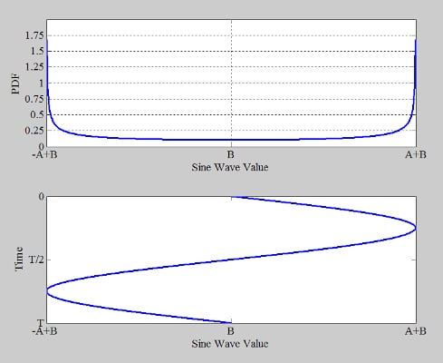
Figure 2. Top plot: results of Equation 6. Bottom plot: rotated sine wave.
The figure demonstrates that the points near zero crossings of the sine wave occur less frequently than the points near the peaks and troughs. This is because the sine wave’s rate of change reaches its maximum at the zero crossings and its minimum at the peaks and troughs. Therefore, the samples around the zero crossings are less likely to occur.
Deriving the Output Histogram
Now that we’ve generated the necessary equations, we can start running tests. We’ll use Equation 3 to construct an output histogram for the ideal 4-bit ADC in Figure 3. Note that Equation 4 would work equally well for our purposes—I simply chose to use Equation 3 for this particular exercise.
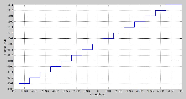
Figure 3. 4-bit ideal ADC transfer function.
Assume the following:
- A sine wave with amplitude A is applied to the ADC.
- The sine wave has no offset error (B = 0).
- The sine wave’s amplitude is greater than the full scale voltage.
Because the sinusoid exceeds the input range of the ADC at both ends, we can be sure that the input exercises all codes of the ADC.
If VLE denotes the first transition point on the left-hand side of the above transfer function, we can use the following equation to find the other transition points:
Equation 7.
The count of the histogram bin corresponding to code 0001, denoted by H(1), is proportional to the probability of the input falling in the region bounded by VLE and (VLE + 1 LSB). Applying Equation 3, we obtain:
Equation 8.
where MT is the total number of samples captured. If we extend Equation 8 to other codes, we can derive an equation for the count of bin n:
Equation 9.
To verify this equation, we’ll use the transfer function in Figure 3 with a full scale voltage of 1 V to digitize a sine wave with the following characteristics:
Amplitude (A) = 1.1 V
Offset error (B) = 0
Frequency = 390.3 Hz
We’ll use a sampling rate of 40 kHz. Note that the input frequency above was chosen so as not to be a subharmonic of the sampling frequency; it is otherwise arbitrary.
By collecting 80,000 samples, we produce the histogram in Figure 4. The red curve plots the values obtained from Equation 9.
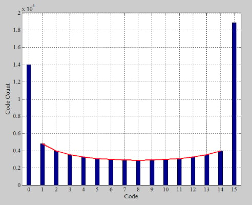
Figure 4. Histogram of digital code occurrences for an ideal ADC. The red curve shows values predicted by Equation 9.
The simulation results are consistent with the values obtained from mathematical analysis. To help you more easily verify this, I’ve provided a summary of the calculations in the following table. Note that VLE = –0.9375.
Table 1. Summary of calculation and simulation results.
|
n |
T[n] |
sin-1(T[n]/A) |
Calculated H(n) |
Simulated H(n) |
|
1 |
-0.8125 |
-0.8310 |
4819.7 |
4816 |
|
2 |
-0.6875 |
-0.6751 |
3970.3 |
3966 |
|
3 |
-0.5625 |
-0.5368 |
3523.3 |
3524 |
|
4 |
-0.4375 |
-0.4090 |
3252.7 |
3252 |
|
5 |
-0.3125 |
-0.2881 |
3080.7 |
3081 |
|
6 |
-0.1875 |
-0.1713 |
2973.5 |
2970 |
|
7 |
-0.0625 |
-0.0568 |
2914.2 |
2914 |
|
8 |
0.0625 |
0.0568 |
2895.3 |
2897 |
|
9 |
0.1875 |
0.1713 |
2914.2 |
2915 |
|
10 |
0.3125 |
0.2881 |
2973.5 |
2978 |
|
11 |
0.4375 |
0.4090 |
3080.7 |
3081 |
|
12 |
0.5625 |
0.5368 |
3252.7 |
3256 |
|
13 |
0.6875 |
0.6751 |
3523.3 |
3523 |
|
14 |
0.8125 |
0.8310 |
3970.3 |
3973 |
The code counts predicted by the mathematical analysis are close to, but not quite the same as, those from the simulation. This is because histogram testing is a statistical method. As such, a larger number of samples should increase the accuracy of the measurement.
Finding DNL Error Using Sinusoidal Histogram Method
Consider the non-ideal 4-bit ADC shown in Figure 5 (red curve).
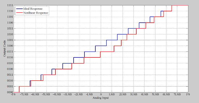
Figure 5. Ideal (blue) and non-ideal (red) response for an example ADC.
The differential nonlinearity (DNL) plot of this ADC is provided below, in Figure 6.
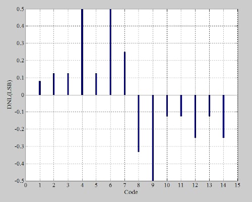
Figure 6. DNL of a non-ideal 4-bit ADC.
As with the ideal case in the previous section, we’ll use the nonlinear transfer function with a full scale voltage of 1 V to digitize a 390.3 Hz sine wave at a sampling rate of 40 kHz. Also as before, A = 1.1 V and B = 0.
Note that the transfer function in Figure 5 has no offset error or gain error. The first and last transitions therefore occur at their ideal values (VLE = –0.9375). Collecting 80,000 samples, we obtain the following histogram (Figure 7).
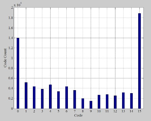
Figure 7. Histogram of digital code occurrences for a non-ideal example ADC.
We exclude the first and last bins, and divide the bin counts by the ideal values given by Equation 9. This gives us the normalized histogram in Figure 8.
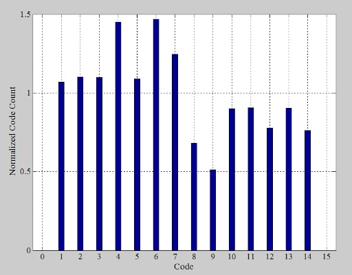
Figure 8. Normalized histogram of digital code occurrences for a non-ideal example ADC.
In the normalized histogram, an ideal code would have a bin count of one. Subtracting one from the bin counts therefore produces the DNL information, which is plotted by the red bar graph in Figure 9. The blue bar graph shows the actual DNL errors.
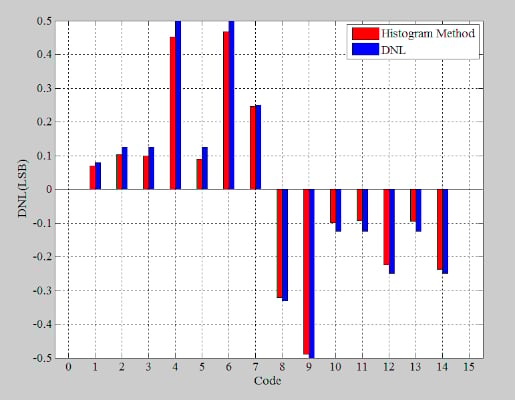
Figure 9. Red: DNL response for an example ADC according to a sinusoidal histogram test. Blue: Actual DNL response for the same example ADC.
Again, the results of the histogram method are close to the actual values but not exactly the same. Correctly choosing different test parameters can increase the accuracy over a given test time. A thorough analysis of the effect of different test parameters on the accuracy of the histogram method is a relatively complex statistical problem involving confidence levels, probabilities, and other factors. I’ll recommend some further reading material in the next section for those interested in obtaining a deeper understanding of these effects.
Nonidealities and Reading Recommendations
In the above examples, we used a theoretical ADC with no gain error or offset error. We also used a sine wave with a known amplitude and zero offset. In practice, the ADC might have both offset and gain errors, and we might not know the exact amplitude or offset error of the input. These nonidealities can make the normalization equations more complicated.
To learn how these effects should be taken into account, you can refer to “An Introduction to Mixed-Signal IC Test and Measurement” by Mark Burns and Gordon W. Roberts. For a thorough discussion on choosing different test parameters such as the required amount of overdrive and the number of samples, you can refer to “Histogram Measurement of ADC Nonlinearities Using Sine Waves” by J. Blair and “Full-Speed Testing of A/D Converters” by J. Doernberg, H. S. Lee, and D. A. Hodges.


