Histogram ADC Testing: The Linear Ramp Histogram Test
Histogram testing is the most popular method for determining analog-to-digital converter (ADC) static parameters. In this article, learn the basics of histogram testing and the specifics of how to use a linear ramp histogram test.
Static linearity testing is important to the economics of analog-to-digital converter (ADC) manufacturing, which is why researchers in academia and industry have put a significant amount of work into developing more efficient ADC testing methods.
A previous article in this series introduced the servo-loop method for testing ADC static parameters. In this installment, we’ll discuss the histogram method in general and explore the uses of a linear ramp histogram test in particular.
First, though, let’s take a look at the major shortcomings of the servo-loop method that made developing this alternative testing method necessary.
Servo-Loop Method: ADC Noise Effect
While the servo-loop method is a popular industrial testing technique, it doesn’t provide optimal efficiency for ADCs with large, input-referred noise. Its accuracy over a given measurement time falls significantly short of the Cramér-Rao bound, which represents the theoretical optimum accuracy. Figure 1 compares the performance of a servo-loop test, denoted as the “conventional” plot, with the accuracy predicted by the Cramér-Rao bound.
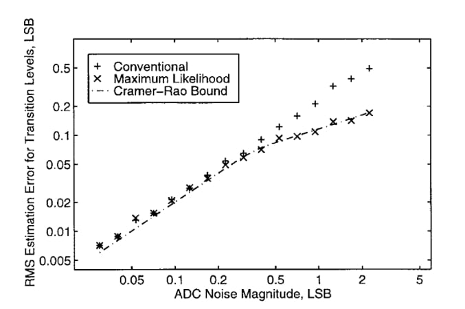
Figure 1. Servo-loop test performance accuracy compared to the theoretical optimum. Image used courtesy of P. Capofreddi
As you can see, the servo-loop method can’t provide optimal efficiency at higher noise levels.
The servo-loop method might work satisfactorily for a 14-bit ADC with low enough input-referred noise. However, many of today’s high-resolution ADCs have a high input bandwidth, leading to peak-to-peak, input-referred noise in excess of 2 LSB (least significant bits). This is why we need testing methods that can derive the ADC transfer function regardless of its noise level.
Histogram Testing of ADCs
Also known as the code density test, the histogram test is by far the most popular method for testing ADC static parameters. The accuracy achieved by this method over a given measurement time is very close to the theoretical optimum value specified by the Cramér–Rao bound (Figure 2).
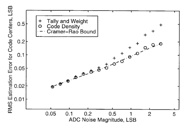
Figure 2. Histogram test performance accuracy compared to the theoretical optimum. Image used courtesy of P. Capofreddi
Unlike the servo-loop method, which directly measures the ADC transition points, the histogram method uses a statistical analysis of the converter output to determine the transition points. Figure 3 illustrates the basic idea behind histogram testing.
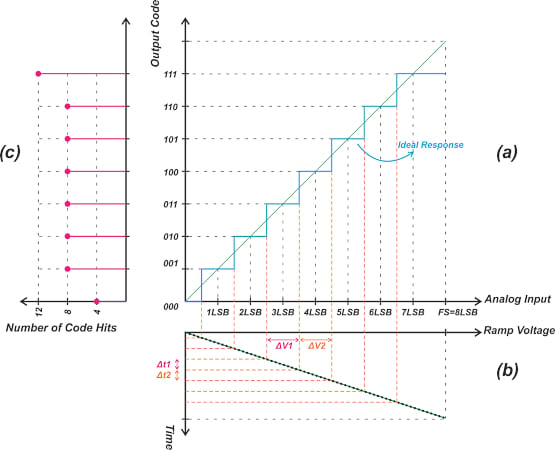
Figure 3. Clockwise from top right—the transfer characteristic of an ideal 3-bit ADC, the rotated waveform of a full-scale ramp applied to the ADC input, and the rotated histogram of that waveform. Image used courtesy of Steve Arar
Figure 3 can be divided into three plots, indicated above by letter designations. Figure 3(a) shows the transfer characteristic of an ideal 3-bit ADC. Figure 3(b) shows the rotated waveform of a full-scale ramp applied to the ADC input. The ramp is assumed to have a fixed slope; we know that the transfer function of an ideal ADC has uniform steps.
For example, consider the step corresponding to codes 011 and 100. These two steps have the same width, so the ramp signal should produce the same voltage change between the steps’ transition points (
. This means that the ramp input falls within the input range of different codes for the same amount of time. In other words, the ADC spends the same amount of time at each of the output codes.
Based on this observation, we can collect a large number of output samples and create a histogram of code occurrences. Each “bin” in the histogram represents an output code, and the count of each bin gives the number of times that code occurs. This count is proportional to the width of the corresponding step in the ADC transfer function.
Figure 3(c) shows the rotated histogram for this example—note that the bins corresponding to codes 001 through 110 all have the same count (8, in this example). Since the first and last steps in the ideal ADC are normally defined as having a width of 0.5 LSB and 1.5 LSB, the counts for the bins corresponding to codes 000 and 111 are, respectively, 4 and 12.
One could argue that the first and last codes don’t actually have a defined width, since the first code doesn’t have a lower bound and code 111 doesn’t have an upper bound. If the input overdrives the ADC, these two codes can occur more often than expected. In fact, in practical histogram testing, the amplitude of the ramp input is chosen to slightly exceed both ends of the ADC input range. This is done to ensure that the input signal exercises all codes of the ADC. As a result, the first and last bins are normally ignored in the histogram method.
Input Signals Commonly Used in Histogram Testing
The test illustrated in Figure 3 is known as the linear ramp histogram test. As that name suggests, it uses a ramp input. However, the input for a histogram test doesn’t have to be a ramp—sinusoidal inputs are a common choice, and any input with a known probability distribution function (PDF) can be used. We only need to compute the output PDF that an ideal ADC produces for the type of input signal used in the test. Next, comparing the measured output histogram with the theoretical one, we can determine the actual transition points of the ADC.
Using a Linear Ramp Histogram Test to Find DNL Error
Now that we’ve discussed the theory behind histogram testing, let’s use the histogram method to find the differential nonlinearity (DNL) error of an example ADC.
To start with, consider the non-ideal 3-bit ADC shown in Figure 4 (red curve).
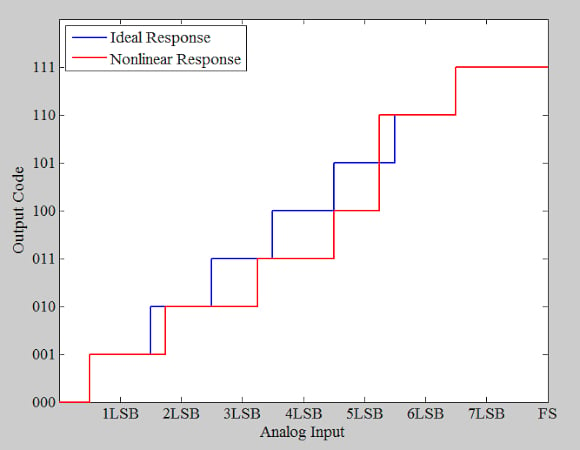
Figure 4. Ideal (blue) and non-ideal/nonlinear (red) example ADC response. Image used courtesy of Steve Arar
The DNL plot of this example ADC is provided below, in Figure 5. Note that code 5 (101) is missing.
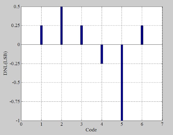
Figure 5. Differential nonlinearity of the example ADC. Image used courtesy of Steve Arar
Now, using the above transfer function with a full-scale range of 1 V, we’ll digitize the periodic ramp at a sampling rate of 40 kHz. Figure 6 shows the result.
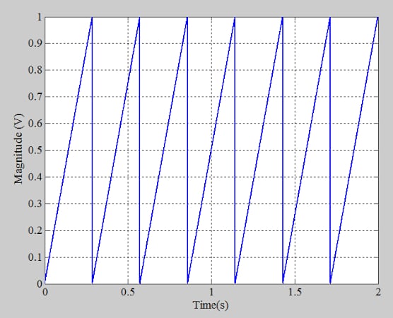
Figure 6. Repeating periodic linear ramp input for example ADC histogram test. Image used courtesy of Steve Arar
The ramp period (0.29 seconds) is much larger than the time between the samples, which can be described using the following equation:
where:
T is the time between samples in seconds
fs is the sampling frequency in Hz.
In other words, the ramp input changes slowly with respect to the ADC sampling rate. This allows each ADC code to be “hit” several times.
If we collect 80,000 samples, we obtain the histogram shown in Figure 7.
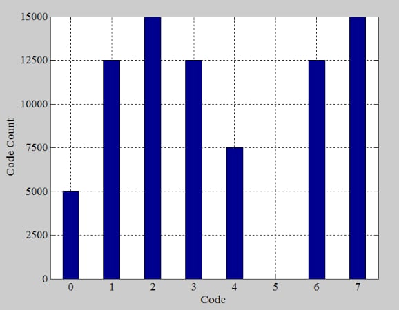
Figure 7. Histogram of digital code occurrences for the example ADC. Image used courtesy of Steve Arar
Bin 5 has a zero count, showing that code 5 (101) is missing. Examining the ideal ADC response (the red curve in Figure 4) reveals that the width of an ideal step is equal to the voltage spacing between the first and last transition points divided by the number of steps in between:
Put differently, the width of an ideal step is equal to the average width. The number of times that codes possessing the ideal width (DNL = 0) occur is therefore equal to the average code count per bin. Excluding the first and last bins, we can calculate the average number of hits per bin as:
Dividing the bin heights by the average code count gives us the normalized histogram in Figure 8.
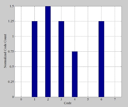
Figure 8. Normal histogram distribution for example ADC test. Image used courtesy of Steve Arar
The normalized histogram specifies the code width in least significant bits, and we determined previously that ideal steps have a height of 1 LSB. Knowing that, we can produce the DNL information (Figure 9) by subtracting 1 LSB from the normalized bin counts of Figure 8. Our results here are consistent with the DNL plot in Figure 5.
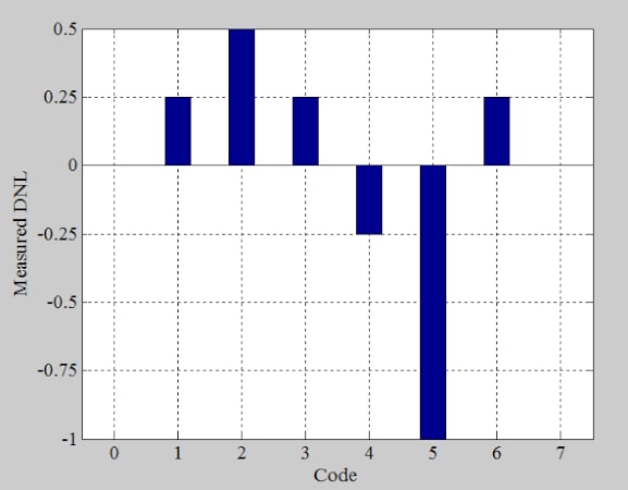
Figure 9. DNL for the example ADC. Image used courtesy of Steve Arar
With proper precautions, the linear ramp histogram method can be used to measure the differential nonlinearity of ADCs with 16 bit or higher resolution. Accurately measuring integral nonlinearity (INL) is more challenging.
Using a Linear Ramp Histogram Test to Measure INL
The INL specification describes the deviation of the actual transfer function’s transition points from the ideal values. The INL is the cumulative effect of the DNL errors, so the INL of the m-th code can be found by applying the following equation:
In principle, the DNL information can be plugged into the above equation to determine the INL error. In practice, however, there are several error sources that prevent us from measuring INL accurately.
The variation of test circuit parameters and ADC characteristics contribute to INL measurement errors. The test circuit variations can come from the power supply, the voltage reference, or the input signal generator; changeable ADC characteristics include the offset and gain.
The summation in the equation above inherently accumulates all of these errors over the measurement time, potentially leading to erroneous results for linearities above 10 bits.
A slow measurement system can exacerbate the drift issue—if it can’t keep up with the ADC’s high sampling rate, gathering the required number of samples will require a longer measurement time. If the drift error is the limiting factor, we could use a fast Fourier transform (FFT) test to measure the ADC harmonic distortion, which is the principal effect of INL. FFT tests require a much smaller number of samples, making them less sensitive to drift.
Additionally, a linear ramp histogram test assumes that the input ramp is perfectly linear. Any nonlinearity in the input directly translates to an error in our INL measurements. This limits the use of the ramp histogram-based INL measurement to ADCs of 12 bits or so. To get around this problem, we can use a sinusoidal input for the histogram test, since low-noise, pure sinusoidal inputs can be easily generated.
Up Next
In this article, we focused on the linear ramp histogram test—both its usefulness and its limitations. Next time we’ll discuss the sinusoidal histogram test, which addresses some of those limitations.


